|
|
Toy SMPS (or: Overkill White LED Driver) |
|||
|
Digitally controlled switchmode power supplies are pretty routine: read the output voltage or current or whatever with an ADC, do some kind of DSP for the control loop, and then use that to set the duty cycle of the switches (or the voltage that sets the peak inductor current or etc.). This was mostly an artificial exercise to see how many corners I could cut and still get something that kind of works. I chose an ATtiny15 for all the control logic. The ATtiny parts have a very convenient on-chip 16× PLL that generates a fast clock just for the PWM peripheral. That means that using the internal RC oscillator for the system clock you can still get decent resolution running the PWM peripheral around 100 kHz.
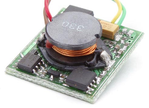
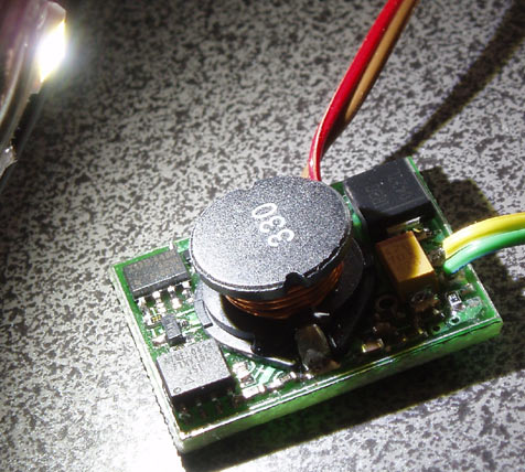
The board is about the same size as a two-euro coin. The assembled unit will fit within an 0.900″×1.100″×0.350″ box. The topology is either boost (with negative ground) or invert (with positive ground), depending on how you look at it. I used a FET and a Schottky; I didn't see how to generate the gate drive for a synchronous rectifier without adding lots of parts count. Neither terminal of the current sense resistor is grounded. I used the fairly-terrible on-chip differential amplifier to accomodate that. It works pretty well. I sense the load current and control the duty cycle. The PWM pin on the AVR drives the gate of the FET through a couple of BJTs. Note the absence of any input capacitance; Vin looks terrible but it works. The micro power supply section is isolated with an RC. Note also the very small output capacitor. I think I imagined this as a battery charger or a LED driver or something, at any rate something where the output voltage holds itself kind of constant already and ripple doesn't matter. It makes a lovely white LED driver:
The LED is an Osram LW W5SG-GYHY-5K8L, a 1 W LED. It is mounted on a scrap of 2 ounce FR4 for heat sinking. This unit could actually drive several 1 W LEDs, or one 5 W emitter (like the newest Luxeons). It's bad to stare into the light. I used the invert (buck-boost) topology, which allows Vin to be either greater than or less than Vout. I could use that to run a white LED (voltage drop around 3 V) from three alkaline cells, which give 4.5 V with a fresh battery down to 2.4 V at 0.8 V/cell. There is a four-switch topology that a lot of ICs use that would be more efficient, but that would be complicated with discretes. The control loop is very ordinary. Mostly it is just slow. I put plenty of capacitance on the ADC inputs, and then I average it more in software. The transient response is not so pretty, but it gets there eventually. The V-I characteristics of the white LED are steep enough that just a little bit of noise on the duty cycle corresponds to quite a lot of variation in the LED current. I have an 8-bit PWM peripheral, and variations of even just a few LSB are visible as flicker.
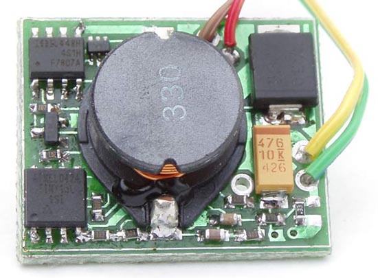
The inductor is obviously the large component in the centre. From the bottom left moving clockwise, we see the AVR, a discrete 2N3904-like BJT, the power FET, a 2N3904/06-like BJT pair, a power Schottky, and a C-size tantalum. A low ESR aluminum electrolytic would probably be smarter. Passives are 0603; there's a couple extra passives on the back to fix mistakes. There was no room for an ISP connector on-board. Pogo pins on the programming jig snap into vias on the SMPS board. I had the programming jig plus a bunch of the SMPS boards made by Olimex, all on a single Eurocard-sized panel. They are slow but very cheap. At a bit less than 5 W output, efficiency is around 72%, inverting 5 V into -5 V. Equivalently, that is around 86% boosting 5 V to 10 V at 10 W output. I don't think that is unusually good or bad. The bill of materials cost is actually not terrible; the micro plus FET does not necessarily cost more than a commercial SMPS chip. It is more flexible—you can make it blink the LED, terminate the battery charge on some condition, or whatever—and it is probably more available too. You can customize just about anything in software; it is very convenient. Looking at the prices of commercial LED drivers, either there's quite a lot of markup or this is a fairly cost-effective solution. Atmel has an app note on something like this but their control loop is boring, with no voltage feedforward control or anything. April 2005, Waterloo |